
Usage of Graphic Organizers in Science and Technology Lessons”, Procedia - Social and Behavioral Sciences, 116, 4264-4269. R&D spillovers and the geography of innovation and production, The American Economic Review, 86(3), 630-640.Īyverdia, L., Nakiboğlu, C., & Aydın, S.Ö.Z. The vital role of problem-solving competence in new product success, Journal of Product Innovation Management, 28(1), 81-98. Income and democracy, American Economic Review, 98(3), 808-842. Fishbone diagram, General purpose technology, Source of technical change, Management of technology, Technology evolution, Evolution of technology.

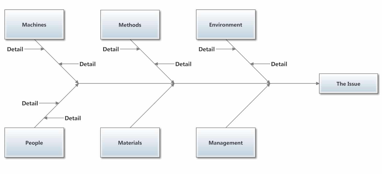
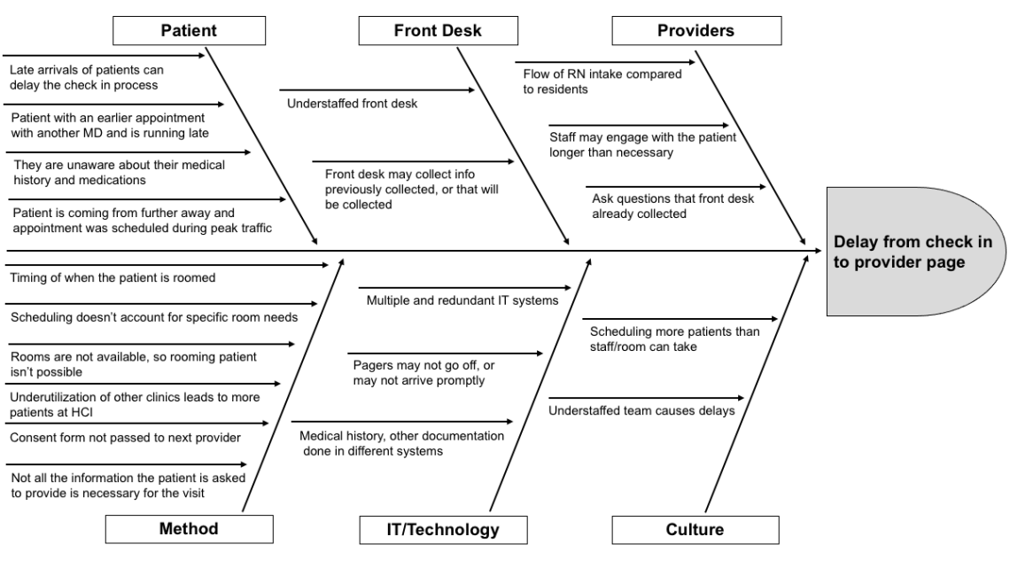
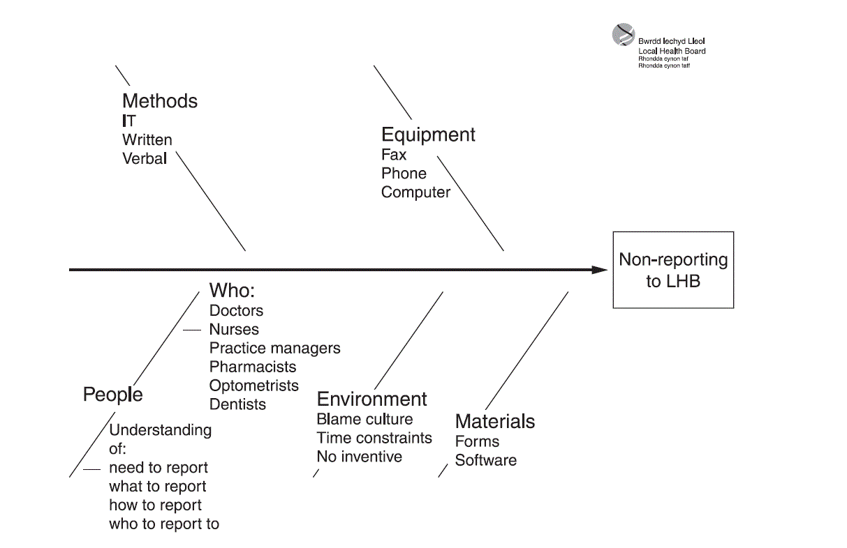
Overall, then, fishbone diagram seems to be an appropriate and general technique of graphical representation to explore and categorize, clearly and simply, the potential root causes of the evolution of technological innovations for an appropriate management of technology. Fishbone diagram is applied here as a novel graphical representation to identify, explore and analyse whenever possible, the potential root causes of the source and evolution of General Purpose Technologies (GPTs). The fishbone diagram can be a comprehensive theoretical framework to represent and analyze the sources of innovation. In particular, a fishbone diagram (the shape is similar to a fish skeleton) is a common tool used for a cause and effect analysis to identify a complex interplay of causes for a specific problem or event. Fishbone diagram (also called Ishikawa diagrams or cause-and-effect diagrams) is a graphical technique to show the several causes of a specific event or phenomenon.

This study suggests the fishbone diagram for technological analysis. When the group runs out of ideas, focus attention on areas in the chart where ideas are thin.Abstract.Layers of branches indicate causal relationships. Continue to ask “Why?” and generate deeper levels of causes. Write sub–causes branching off the causes. Ask the question “why does this happen?” again.Causes can be written in several places, if they relate to several categories. Ask: “Why does this happen?” As each idea is given, the facilitator writes it as a branch from the appropriate category. Write the categories of causes as branches from the main arrow.For instance, it might make sense to start with these generic headings: methods, machines (equipment), people (manpower), materials, measurement, and environment. Brainstorm the primary categories of causes for the problem.Write the problem statement at the center-right of the flipchart or whiteboard, box it, and draw a horizontal arrow running to it.The group should agree on a problem statement (effect).The purpose of the Ishikawa diagram is to allow management to determine which issues have to be addressed in order to gain or avoid a particular event. They are causal diagrams created by Kaoru Ishikawa to show the causes of a specific event. They resemble a fish skeleton, with the "ribs" representing the causes of an event and the final outcome appearing at the head of the skeleton. Ishikawa diagrams are sometimes referred to as fish bone diagrams, herringbone diagrams, cause-and-effect diagrams, or Fishikawa. Ishikawa diagrams often follow the "Six M's": manpower, machinery, methods, materials, measurement, and mother nature.Shaped somewhat like a fish, these charts are sometimes called fishbone or "Fishikawa" diagrams.They are named after Japanese engineering professor Kaoru Ishikawa in the 1960s, who helped apply them to manufacturing processes.An Ishikawa diagram is used to show the causal factors that go into some final outcome, often related to a production or design problem.


 0 kommentar(er)
